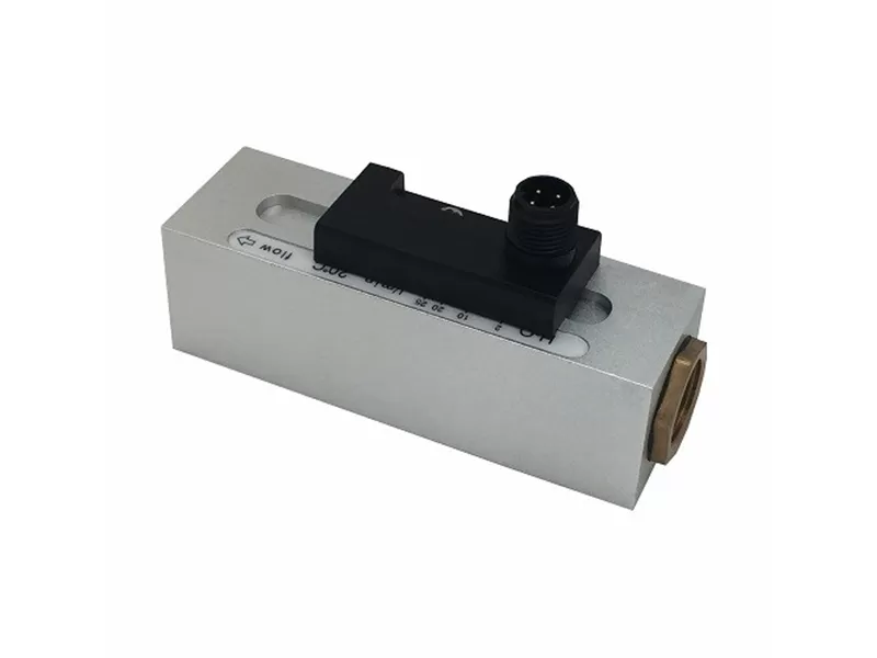
FS200
Piston Flow Switch
Principle and Structure: Online installation, mechanical flow switch, Be used in liquid or gas media. Solid plastic, aluminum or stainless steel housing are optional.
Main Feature: Very few pressure loss, satisfactory repeatability and anti-pollution, mechanical and electronic parts are isolated completely. More accurate setting accuracy, with setting dial gauge, easy setting, user no need to set on site, switch status displays in LED.
Application: Can be used in both gas and liquid, industrial automation, mechanical equipment, air compressor industrial, HVAC.
Parameters
| General | Value |
| Setting Range | see specification sheet |
| Accuracy | ±5% total range |
| Delay | Depend on different switches, Minimum 0.5L/Min |
| Setting Scale | 20℃ water as media, horizontally installation in marked position |
| Change of media and temperature can infuence the value | |
| LED display | Only available in DC distributing |
| Terminal | M12 and Hirschmann plug |
| Output | Reed switch, capacity: 24VDC/250VAC, 100mA |
| Proof Pressure | 50bar(aluminum) 200bar(stainless steel) |
| Average Pressure Loss | 0.3bar(25L/min) |
| Return Difference | Related to the switch value, minimum 0.5L/Min |
| Temperature of meda | 0-100℃/0-160℃ (high temperature option) |
| Protection Degree | IP65 |
| Engineering Plastic Materials | Housing: POM engineering plastics |
| Plunger: POM engineering plastics | |
| Spring: 316L stainless steel sus1.4310 | |
| Seal: NBR | |
| Magnet: Barium | |
| Anodic Aluminum Oxide Materials | Housing: Anodic Aluminum Oxide |
| Plunger: POM engineering plastics | |
| Spring: 316l stainless steel SUS1.4310 | |
| Seal: NBR | |
| Magnet: Barium | |
| Stainless Steel Materials | Housing: 304 stainless stee |
| Plunger: POM engineering plastics | |
| Spring: 316L stainless steel SUS1.4310 | |
| Seal: NBR | |
| Magnet: Barium |
| Anodic Aluminum Oxide Materials (Stainless Steel) | Model | Proof Pressure | Maximum Flow | Changeable Range | G | L | H | B | X | Weight | |
| Kg | L/min(water) | L/min(water) | mm | mm | mm | mm | mm | ||||
| FS201. 202 203 | Maxinmun 200 Kg | 40 | 0.6(0.1) | 8(7) | G1/4 | 93 | 30 | 12 | 0.22 (0.53) | ||
| 0.6(0.1) | 8(7) | G3/8 | 15 | 0.20 (0.51) | |||||||
| 0.6(0.1) | 8(7) | G1/2 | 0.18 (0.48) | ||||||||
| 0.6(0.1) | 8(7) | G3/4 | 105 | 35 | 0.23 (0.65) | ||||||
| 0.6(0.1) | 8(7) | G1 | 105 | 40 | 0.32 (0.82) | ||||||
| 1(0.5) | 15(13) | G1/4 | 93 | 30 | 12 | 0.22 (0.53) | |||||
| 1(0.5) | 15(13) | G3/8 | 15 | 0.20 (0.51) | |||||||
| 1(0.5) | 15(13) | G1/2 | 0.18 (0.48) | ||||||||
| 1(0.5) | 15(13) | G3/4 | 105 | 35 | 0.23 (0.65) | ||||||
| 1(0.5) | 15(13) | G1 | 105 | 40 | 0.32 (0.82) | ||||||
| 2(0.8) | 28(25) | G1/2 | 93 | 30 | 0.18 (0.48) | ||||||
| 2(0.8) | 28(25) | G3/4 | 105 | 35 | 0.23 (0.65) | ||||||
| 2(0.8) | 28(25) | G1 | 40 | 0.32 (0.82) | |||||||
| 27(21) | 70(66) | G3/4 | 35 | 0.23 (0.65) | |||||||
| 27(21) | 70(66) | G1 | 40 | 0.32 (0.82) | |||||||
Remark:
1. Data in above parentheses is reset point while the other is operating point, Please refer to reset point data while in lower limit alarm(monitoring too small fow), and refer to operating point data while in upper limit alarm(monitoring too large flow).
2. Above data is based on the test that switch is installed on horizontal pipe vertically and use 20℃ water as media.
3. Above proof pressure data is based on 304 stainless steel materials, proof pressure 50bar, 20bar are optional either.
Dimension


